
MODULE 3: FOUNDATIONS OF ELECTRICITY
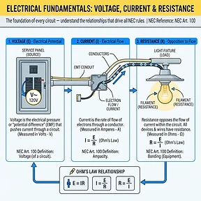
FIG · Article 100
FUNDAMENTALSArticle 1008 min read
Electrical Fundamentals: Voltage, Current & Resistance
Master electrical fundamentals of voltage, current, and resistance to understand NEC compliance and safe circuit design for field applications.
YOUR PROGRESS
REAL-TIME METRICSACADEMY
0/168
0% complete
FOUNDATIONS OF ELECTRICITY
1/8
0 of 8 done
QUIZ SCORE
—
Not attempted yet
Learning objectives - Calculate unknown electrical values using Ohm's Law and the Power Formula. - Analyze the relationship between conductor resistance and heat generation in branch circuits. - Distinguish between electrical pressure and electron flow in common circuit applications. - Apply NEC definitions to interpret load requirements for branch circuit protection. - Identify the impact of voltage drop on conductor sizing and circuit efficiency. - Demonstrate proficiency in troubleshooting circuits by verifying voltage and resistance measurements. ## Why this matters in the field Electrical troubleshooting is effectively the practice of finding out why the three pillars of electricity—voltage, current, and resistance—are out of balance. When a breaker trips or an appliance fails to run, the electrician is actually hunting for an open circuit, a short, or an unwanted resistance. If you do not have a firm grasp on the mathematical relationship between these variables, you are merely guessing, which leads to wasted time and dangerous guesswork. The cost of getting it wrong is high: incorrect conductor sizing leads to excessive heat, which degrades insulation over time, leading to arc faults and catastrophic fire hazards. Beyond safety, a failure to understand these basics results in high voltage drop, which kills expensive motor equipment and causes flickering lights, leading to callback costs that erode your profit margins on every job. By mastering these concepts, you transition from someone who just pulls wire to a technician who understands why the Code demands specific protections. ## Core concepts ### Defining Electromotive Force Voltage, commonly referred to as potential difference or electromotive force, is the electrical pressure that causes electrons to move through a conductor. Think of it like water pressure in a pipe; without pressure, there is no flow. In the NEC context, voltage is the primary factor in determining the insulation rating of conductors and the spacing requirements for clearances in electrical equipment. When we speak of a 120V system, we are referring to the potential difference between the hot conductor and the grounded conductor. Ignoring voltage ratings is a primary cause of insulation breakdown, where the pressure is too high for the dielectric material, resulting in a flashover. ### The Nature of Current Flow Current is the actual movement of electrons, measured in amperes. While voltage is the potential push, current is the work performed by that push. In the NEC, current is the foundation for conductor ampacity. Article 100 defines the relationship between the load and the protection device. When current flows, it generates heat due to the friction of electrons passing through the atomic structure of the wire. If the current exceeds the ampacity listed in the NEC tables, the insulation reaches a point of thermal degradation. This is why overcurrent protection is mandated at the point of supply for every circuit. ### The Mechanics of Resistance Resistance is the opposition to the flow of current. Every material has a resistance value based on its atomic structure, length, cross-sectional area, and temperature. In residential and commercial wiring, resistance is typically a negative variable—it is unwanted, as it converts electricity into waste heat. NEC Article 210.19(A)(1) Informational Note 4 regarding voltage drop is fundamentally a lesson in resistance management. When a connection is loose, the resistance at that specific point increases significantly. This localizes heat, which causes expansion and contraction, eventually loosening the terminal further. This vicious cycle, known as high-resistance heating, is a leading cause of residential electrical fires. ### Power and Energy Relationships Power, measured in watts, is the product of voltage and current. It represents the rate at which electrical energy is converted into other forms, such as heat, light, or mechanical motion. The NEC requires us to calculate loads in volt-amperes (VA) to account for the phase angle differences in inductive loads, but the fundamental physics remain P equals V times I. When a circuit is overloaded, the total power required by the connected devices exceeds the circuit's capacity, forcing the overcurrent protection device to open. Failure to balance power demands can result in erratic system performance and potential damage to sensitive electronic components that rely on stable voltage. ## Code requirements NEC Article 100 provides the definitions for branch circuits and feeders that rely on these fundamentals. Paraphrased, Article 210 requires that conductors be sized to carry the load, and that the protection device must be sized according to the conductor ampacity as established in Article 310. The NEC limits current based on ambient temperature and the number of current-carrying conductors in a raceway, which are adjustments for the heat generated by current and resistance. Exceptions are often applied by inspectors regarding continuous loads, which must be calculated at 125 percent of the actual load to prevent the overcurrent device from nuisance tripping due to heat buildup. ## Step-by-step method 1. Verify voltage presence at the load side of the breaker using a calibrated multimeter. 2. Calculate the expected current draw using the power rating of the load (I = P/V). 3. Measure the actual current draw using a clamp-on ammeter to confirm the load is within the 80 percent continuous load limit if applicable. 4. Check for loose connections or high resistance at every splice or terminal block using a milliohm meter if overheating is suspected. 5. Perform a voltage drop test under full load to ensure the resistance of the circuit wiring does not exceed the recommended 3 percent limit. 6. Verify that the breaker size matches the conductor ampacity rating found in NEC Table 310.16. ## Worked examples 1. Simple Load: A heater is rated at 1,500 watts and operates on a 120V circuit. I = 1,500W / 120V = 12.5 Amps. This is a straightforward application of Ohm's Law. 2. Derating: A circuit carries a continuous load of 16 Amps. NEC requires a 125 percent safety factor for continuous loads. 16A x 1.25 = 20A minimum circuit protection. Using Table 310.16, we select 12 AWG copper, which is rated for 20A in the 60-degree column. 3. Resistance Trap: A 100-foot run of 14 AWG copper wire has a resistance of approximately 0.25 ohms. If the current is 15A, the voltage drop is V = 15A x 0.25 ohms = 3.75V. If the supply is 120V, the device receives 116.25V. If the voltage drops too low, the device may overheat trying to maintain power, illustrating the trap of neglecting resistance over distance. ## Field scenarios 1. Flickering Lights: Found 110V at the panel but only 95V at the fixture. Identified a loose neutral connection in a junction box. Tightening the connection removed the high-resistance point and restored full voltage. 2. Tripping Breaker: A customer installed a 2,000-watt machine on a 15A circuit. The math (2,000 / 120 = 16.6A) proves the circuit is overloaded. The resolution was installing a dedicated 20A circuit with 12 AWG wire. 3. Motor Stall: An HVAC blower motor hums but won't start. Measured voltage while the switch was closed and found it dropped to 80V. Traced to a corroded contactor, which acted as an unintended resistor, reducing the available voltage for the motor start-up. ## Common mistakes and inspection failures - Using incorrect insulation ratings for the circuit voltage. - Failing to account for terminal temperature ratings (60C vs 75C) when sizing wires. - Ignoring the 125 percent rule for continuous loads on branch circuits. - Improperly bonding neutral and ground, which creates parallel resistance paths. - Assuming all wire lengths have negligible resistance. - Overlooking the impact of ambient temperature on conductor ampacity. - Installing aluminum conductors without approved antioxidant paste, leading to high-resistance oxidation. - Relying on "rule of thumb" sizing instead of calculating actual load in VA. ## Safety notes - Always test for absence of voltage using a properly rated and calibrated meter before beginning work. - Wear appropriate PPE, including arc-flash rated clothing and insulated gloves when working near live parts. - Never attempt to bypass a breaker by installing a larger fuse or higher-rated breaker without re-sizing the wire. - Ensure all grounding paths are intact; an open ground removes the path of least resistance for fault current, risking lethal shock. - Practice lock-out/tag-out (LOTO) protocols to ensure the circuit is de-energized during repairs. ## Exam tips - Memorize the relationship V = I x R and P = V x I; you will use these for almost every math problem. - Always check the temperature rating of the terminals (e.g., 60C or 75C) before looking up values in Table 310.16. - Remember that "Continuous Load" is defined as 3 hours or more; always use the 125 percent multiplier for these. - When calculating voltage drop, remember that the current travels through two conductors (supply and return) for the total distance. ## Key takeaways - Voltage is the pressure; current is the flow; resistance is the opposition. - Ohm's Law and the Power Formula are your primary tools for verifying circuit safety. - Heat is a symptom of energy loss due to resistance or excessive current. - The NEC is designed to manage electrical heat to prevent fire and equipment failure. - Always calculate continuous loads at 125 percent to prevent thermal overload. - A properly installed circuit has low resistance, providing stable voltage to the load.
Related lessons
Could not load quiz. Please try again.